 English
 Español
 Português
 русский
 français
 日本語
日本語 Deutsch
 Tiếng Việt
 Nederlands
 ไทย
ไทย Polski
 한국어
한국어 Svenska
 magyar
 Malay
Malay বাংলা
বাংলা Dansk
Dansk Suomi
Suomi हिन्दी
 Pilipino
 Türk
Türk Gaeilge
 عربى
عربى Indonesia
 norsk
norsk čeština
 Ελληνικά
 Українська
 नेपाली
 Burmese
 български
 ລາວ
ລາວ Latine
 slovenský
 Lietuvos
How is Wire Drawing Die Calculated?
How is Wire Drawing Die Calculated
Wire Drawing Die
Wire drawing dies are essential tools in the metal processing industry, used to reduce the diameter of metal wire through a controlled process. The calculation of wire drawing dies plays a critical role in ensuring efficiency, precision, and quality during production. Understanding the factors that influence die sizing and calculations helps manufacturers achieve optimal results while minimizing costs and waste.
Key Factors in Wire Drawing Die Calculation
1. Material Properties
The type of material being processed is a major factor in wire drawing die calculations. Different metals, such as copper, aluminum, steel, and stainless steel, have varying levels of ductility, hardness, and tensile strength. These properties determine how much reduction the wire can undergo in each pass through the die. For instance, more ductile materials like copper allow for greater reductions in diameter with each pass, while harder materials require smaller, more gradual reductions to avoid wire breakage.
2. Reduction Ratio
The reduction ratio is a key concept in wire drawing, referring to the percentage decrease in wire diameter after passing through the die. It is calculated using the formula:
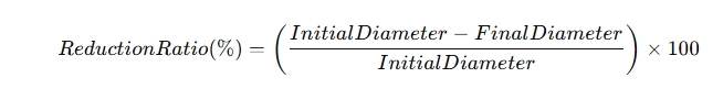
For example, if a wire starts with a diameter of 5 mm and is drawn to a diameter of 4 mm, the reduction ratio is 20%. Knowing the desired final wire diameter and the material's tolerance for reduction allows engineers to determine the number of passes required and the appropriate size for each die in the sequence.
3. Drawing Force
The drawing force is the amount of force required to pull the wire through the die. This is influenced by the material's strength, the friction between the wire and the die, and the reduction ratio. Excessive drawing force can lead to wire breaks or surface defects, so it is crucial to calculate it accurately. The drawing force can be estimated using the following formula:
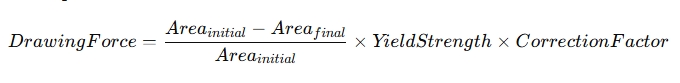
The correction factor accounts for the friction and efficiency of the die, typically ranging from 0.9 to 1.0, depending on the die material and lubrication.
4. Die Angle
The angle of the die is another critical element in wire drawing calculations. A proper die angle ensures smooth material flow and uniform reduction. Typically, smaller die angles are used for harder materials to minimize stress on the wire, while larger angles are suitable for softer materials. Incorrect die angles can lead to excessive wear on the die, increased drawing force, or damage to the wire's surface.
5. Lubrication
Lubrication plays an essential role in reducing friction during the drawing process. The amount and type of lubrication can significantly affect the drawing force and overall efficiency. Insufficient lubrication can lead to higher friction, more heat generation, and premature die wear, while excessive lubrication can lead to slippage, reducing control over the drawing process.
The Importance of Accurate Calculations
Accurate wire drawing die calculations are critical to ensuring high-quality products and efficient production. Overestimating or underestimating key factors such as reduction ratio or drawing force can result in wire defects, equipment damage, or even production downtime. Manufacturers often use computer simulations and advanced software to model the wire drawing process and optimize die designs before beginning production.
In conclusion, wire drawing die calculation involves a combination of material properties, reduction ratios, drawing force, die angles, and lubrication. These factors must be precisely calculated to achieve optimal results in wire manufacturing. As the metal processing industry continues to evolve, advancements in technology and automation are expected to further enhance the accuracy and efficiency of wire drawing die calculations, leading to better products and streamlined operations.

Changzhou Shen Litong Mould invites you to visit the exhibition
From August 27th to 29th, 2025, at SHANGHAI NEW INTERNATIONAL EXPO CENTRE,the 12th China International Wire&Cable Industry Exhibition (Hall E1, G21), Shen Litong Dies sincerely invites you to visit, exchange and offer guidance, and jointly explore new developments in the industry.
Read MoreOptimizing Your Wire Drawing Process: Selecting the Ideal Die Configuration for Material & Application
The wire drawing process is a critical metal forming operation that reduces the cross-section of wire by pulling it through a series of progressively smaller dies.
Read MoreCommon Wire Surface Defects: Causes and Die-Related Solutions
Abrasions or Built-up Edges (BUE): Accumulation of wire material (e.g., copper, aluminum) on the die surface, which then scratches subsequent wire.
Read More